To add Bidule as an audio effect to a Live set, go to the Live Devices browser and choose Audio Units > Plogue > Bidule FX, and add to an existing audio track as per any other audio plugin.
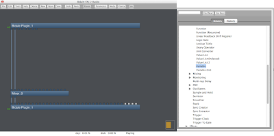
When you open up the Bidule plugin, you are greeted with the default patch. This patch is very simpler. It consists of three Bidule objects:
• An object that represents audio going into Bidule
• A mixer object for setting levels, panning and soloing of multiple audio signals
• An object that represents audio coming out of Bidule.
The signal flows from top to bottom in Bidule - audio enters via the top objects, is routed down through the mixer and then leaves via the lowermost object.
It is important to note that, although Bidule is capable of surround sound processing, Live will send and receive the signals going into and out of Bidule as stereo only. This means that only the first two (representing left and right) inlets and outlets of the plugin input and output object must be used.
Object Parameters
Double clicking on any object will display any parameters associated with that object. For example, we can double click on the mixer object to bring up the Mixer parameters, including eight channel strips. Each channel strip controls one pair of the sixteen individual inputs. Every odd input is a left signal. Every even input is a right signal.
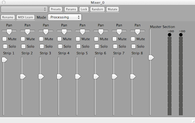
Adding Objects
To add an object, simply connect the outlets of an existing object to the inlets of the object in question. Then, connect the outlets of the object in question to an input. Place the mouse over an outlet or an inlet to determine more information about the inlet type (displayed in the lower left hand of the Bidule plugin window) - whether it expects an audio signal or a data range for a certain function or parameter.
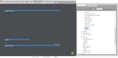
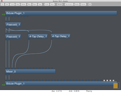
Delete the connections between the Bidule input object and the mixer object. Click on palette to open the object palette, and navigate to Effects > Freeverb. Drag and drop multiple Freeverb object into place, as shown below. Also add two 4-tap Delay Lines into place. Connect as shown.
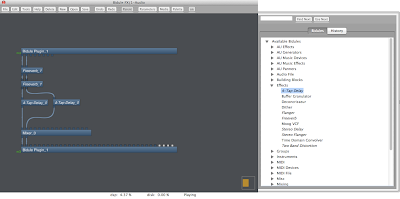
Double click on the Freeverb objects to change their parameters.
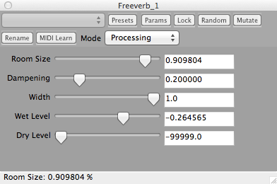
The Freeverb object process sound in stereo (L and R). The 4-Tap Delay objects process sound in mono - hence, two are needed for a stereo signal. Connect the output of the two 4-Tap Delay objects to the first pair of left and right inlets of the mixer object.
Serial Versus Parallel Routing
The example shown previously is a serial example of audio signal processing, in that the output of one effect is routed to the input of another effect - Input > Freeverb > Freeverb > 4-tap Delay > Output. However, with Bidule, we can process multiple streams of the same signal simultaneously - i.e. the output of one of the Freeverb objects can be routed to more than one place for additional processing.
This opens up many more possibilities than would be possible with simple serial connections. A simple example of parallel routing is shown below.
Variables
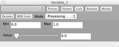
Many objects in Bidule allow for controlling parameters or functions via an inlet. Data can be sent to these inlets to control that particular parameter. By inserting a Variable object from Building Blocks > Math > Variable, a slider and a range of values for the slider can be used as an interface to control effects.

By double clicking on the Variable object, we can set the output value via the slider, in addition to the value ranges of the slider. The default slider data range is 0.00 to 1.00, however these values can be changed.
Consider the Biquad Filter object (Building Blocks > Filters > Biquad Filter). This object has four inlets and one outlet:
• The first inlet is the audio input (for the signal that is to be filtered).
• The second inlet is a data inlet for the frequency control.
• The third inlet is a data inlet for the Q / bandwidth control.
• The fourth inlet is a data inlet for the filter gain control.
• The outlet is for the filtered audio coming out of the filter.

Connect the output of the Variable object to the frequency control inlet of the Biquad Filter. Obviously, we need to change the useable range of the slider - as the default data range is useless. Set the min to 0.00 and the max to 20,000.00, to correspond to a range of 0Hz to 20KHz.

Add variables for the Q and the gain. Set the range to [0 - 10] and [-20 to 20] respectively. The Q is simply in bandwidth amount, and so a range of 0 - 10 makes sense. The gain is simply in dB, and so a range of -20 dB to +20 dB for the filter gain make sense. You can rename Variable objects by control-clicking on them and selecting rename.


1 comments:
Quite a complex concept, but thanks for breaking things down a bit!
-Jackie
Post a Comment