Oscillations
Consider the humble sine wave as we normally might hear and see it. Digitally, this waveform has a range of -1.0 to 1.0. These two extremes represent the maximum and minimum excursions of our speakers, but these values also represent the maximum signal that our digital to analog sound converter can deal with before we get nasty digital distortions.
However, in Bidule we can use our oscillators for control purposes. Rather than just listening to sine tones, we can use sine functions and other waveforms to easily control parameters of various objects.
Process
We can break this process down into a number of easy to understand steps:
• Create an oscillator setup
• Decide where it should be mapped to (i.e. which parameter should be controlled using the oscillator)
• Work out the data range for the mapping (i.e. what are the maximum values that are required for that particular parameter)
• Scale the output of the oscillator so that it is creating a signal that is within our desired data range, and connect the output to the parameter
Creating An Oscillator
Let's work with an example, and use the Biquad Filter from the previous setup, as seen below.
The perfect parameter for us to modulate of the filter is the frequency, of course! The first stage in this process is to create a simple low frequency oscillator (LFO). In Building Blocks > Oscillators, grab the Basic Oscillator object. This is our starting point to creating an LFO.
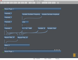
Rename the oscillator object 'LFO'. We are interested in the first two inlets - so create Variables for each of those inlets, and name them 'Variable Oscillator Frequency' and 'Variable Oscillator Amplitude'. Connect them to the oscillator object.
Set the data range for these tow variables to [0 - 20] and [0 - 1], respectively. This gives a frequency range of 20 Hz and an amplitude gain range of 0 to 1.
Why Should We Transform The Data Range?
Although the frequency parameter is obvious, the gain / amplitude parameter may not be. This parameter represents a multiplication factor that is applied to the oscillator's waveform. An amplitude setting of 1.0 means that the output of the waveform is multiplied by one.
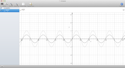
Our sine wave's signal range goes from -1.0 to 1.0; therefore, an amplitude setting of 1.0 will leave this range at -1.0 to 1.0. However, if our amplitude setting is at 0.5, then every point along the sine wave is multiplied by 0.5, resulting in a signal range of -0.5 to 0.5.
Compare the two sine waves shown below as an example - the lighter wave has a range of -1.0 to 1.0, whilst the darker wave has a range of -0.5 to 0.5.

Finally, we need to scale and transform the output of our waveform in terms of the data range that the signal occupies - in other words, a data range of -1.0 to 1.0 may not be suitable for every parameter and every application.
For instance, our frequency input on our Biquad Filter object expects a data value range of 0 to 20,000. If we currently connected our oscillator to this inlet, we would be feeding it with a data source that has a range of -1.0 to 1.0, whereas we need to change our oscillator to sit within the appropriate range.
Scaling the Oscillator Data Range
The most useful object for this purpose is found in Building Blocks > Math > Function. Basically, this object takes up to three inputs - named X, Y and Z - and performs a mathematical function on them, and then sends the resulting data to the outlet.
Don't worry! This sounds complex, but it's really easy - as we're only going to be dealing with the X inlet (the first inlet), and we're only going to be doing simple things to it like addition and multiplication.
Now - let's consider the data range that we have, and the data range that we might like to end up with!
• Our oscillator is currently outputting a signal from -1 to 1
• Our frequency input from the Biquad Filter object has the range of 0 - 20,000 Hz
• However, we might only want a filter that sweeps from 0 Hz to 2000 Hz
So basically, we want to end up with an oscillator that has the signal range of 0 - 2000 instead of -1 to 1. We need to do two things: add something to our oscillator's output, so that we always stay in the positive with our signal (i.e. doesn't go below 0), and also multiply or increase our signal so that it goes all the up to 2000.
Logically, we can think about it this way: let's add 1 to the oscillator signal, and then after that, let's multiply the oscillator signal by 1000.
Double click on the Function object, and enter the expression as an expression of the X inlet. We can write that in the Function object like so: (X + 1.0) * 1000.
What we are saying by typing this into the Function object is: 'Perform this equation on every data value that arrives at the X inlet, and send the resulting value to the outlet'.
Connect the LFO to the Parameter
Now that our oscillator signal is properly scaled, it's time to connect the output of the LFO to the frequency inlet of the Biquad Filter objects, as shown below:
Of course, we can perform this same exercise with any parameter that we normally control with a variable control, opening up many possibilities for control.
Beyond this, also try to experiment with:
• Controlling LFOs using other LFOs
• Send more than one LFO signal to one parameter, but change the frequency, amplitude, etc independently
• Use filtered and scaled audio signals to control parameters of objects


1 comments:
Nice posts Seb. What software are you using to generate those very nice sine wave diagrams?
Post a Comment